Blender watercolor shader (tutorial notes)
Notes from following a watercolor shader tutorial: toon base to watercolor breakup to outlines (inverted hull plus grease pencil) to a quick compositor stack.
- Date
- Sep 2, 2025
Credit (original tutorial)
This entry is based on a tutorial walkthrough. The steps were followed and the node setups were captured as notes along the way.
Initial render settings
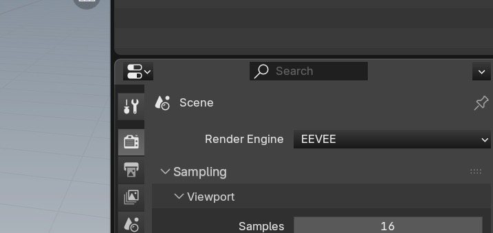
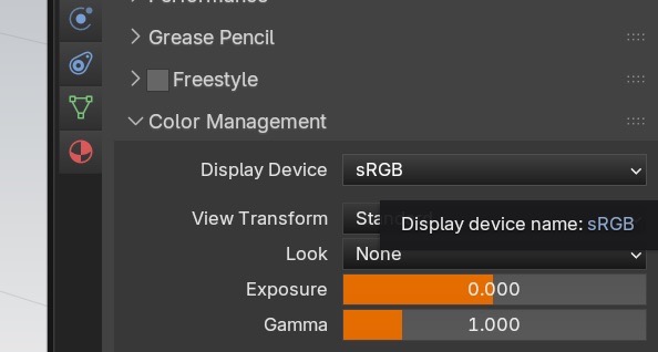
Baseline first. Render Engine set to EEVEE. Color Management, View Transform set to Standard.
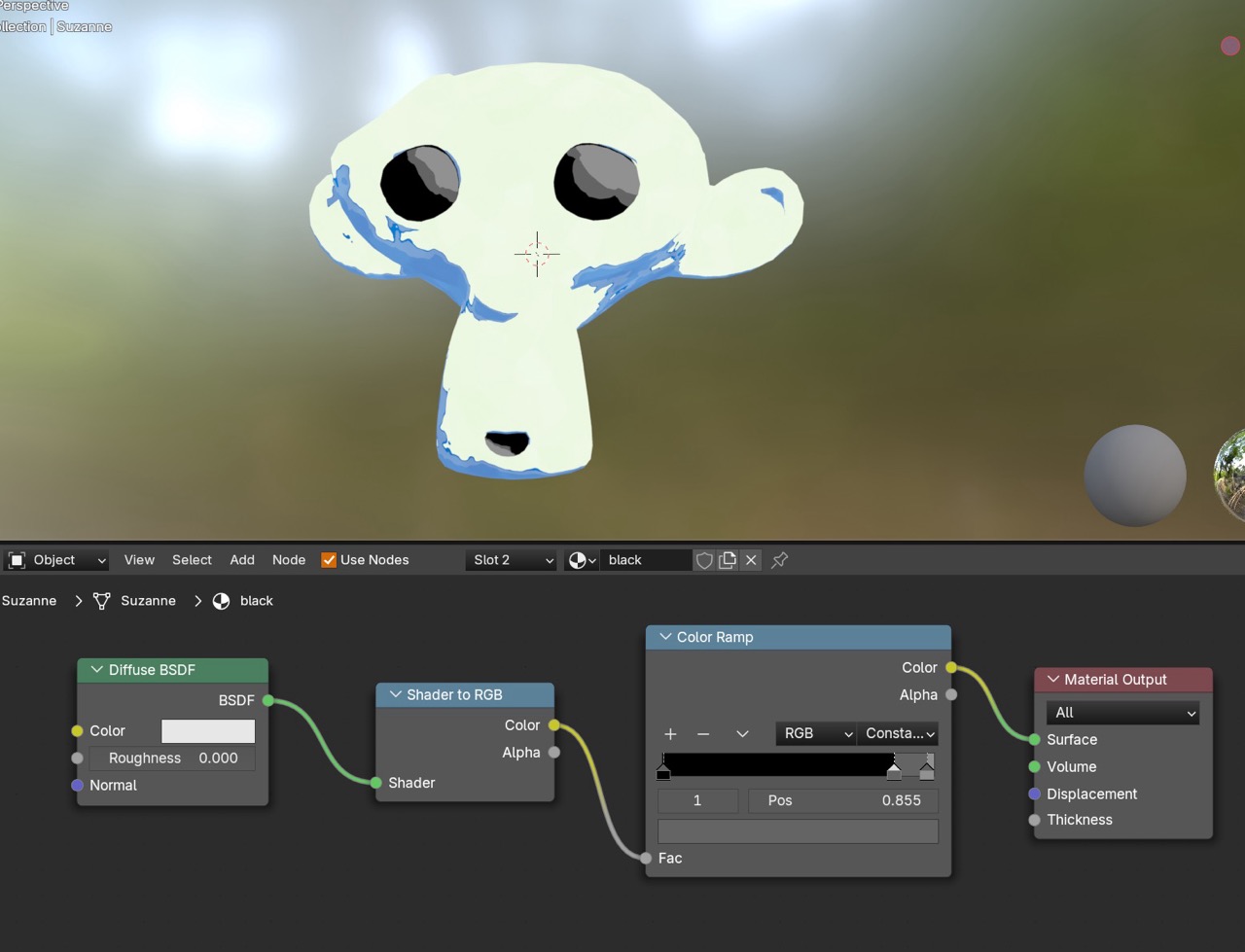
Basic toon shader on Suzanne
Start with a clean toon base. Keep values simple so the watercolor layer has a stable foundation.
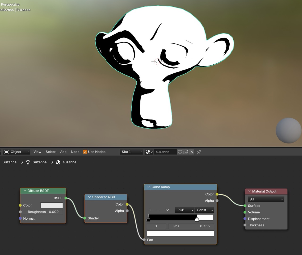
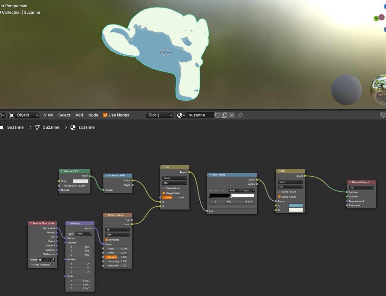
Target here is readability. Controlled shading first. Texture breakup later.
Basic watercolor effect (with Voronoi texture)
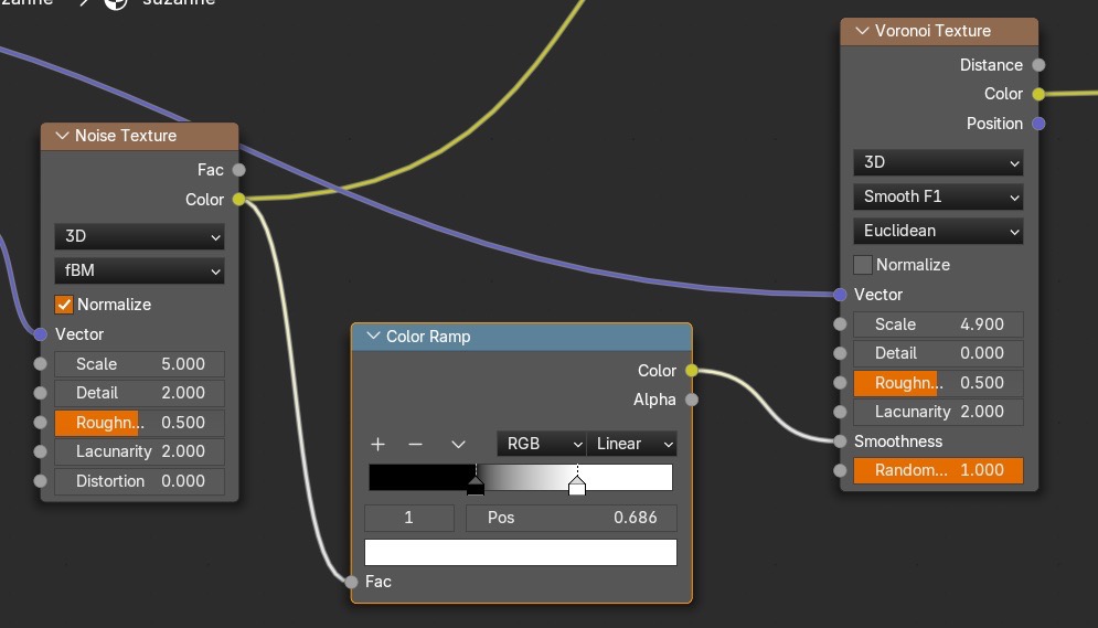
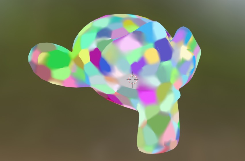
Add Noise plus Voronoi. Drive Voronoi with Noise so the breakup reads as paint patches instead of uniform noise. Connect Noise Vector to Voronoi Vector. Connect Noise Color to Voronoi Smoothness.
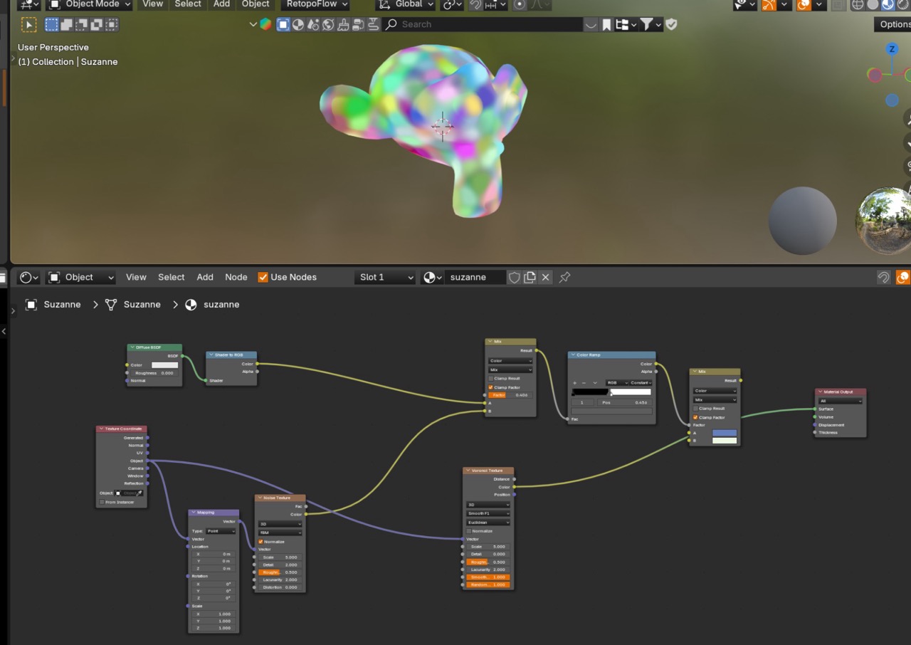
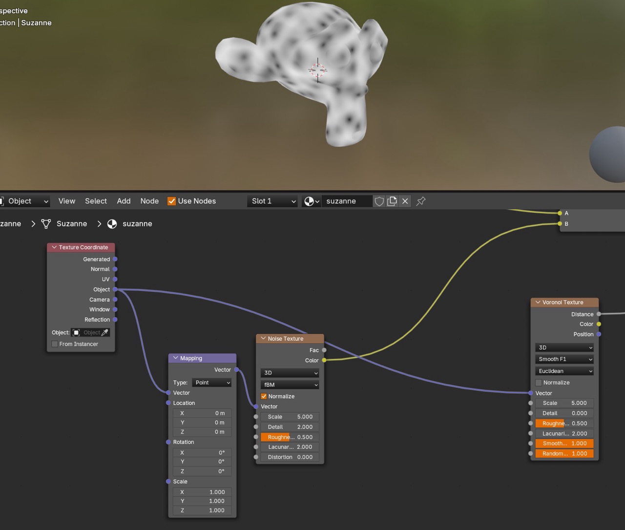
Tune scale until the patches read clearly.
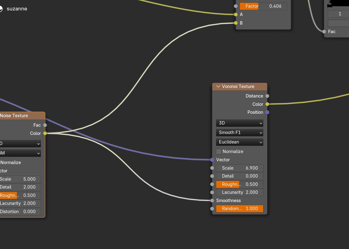
Adjust scale and confirm the breakup behaves as intended.
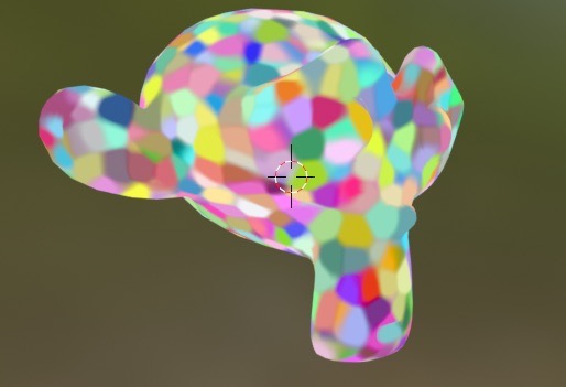
Add a ColorRamp to control how painterly the breakup reads.
Combine toon + watercolor (material output)
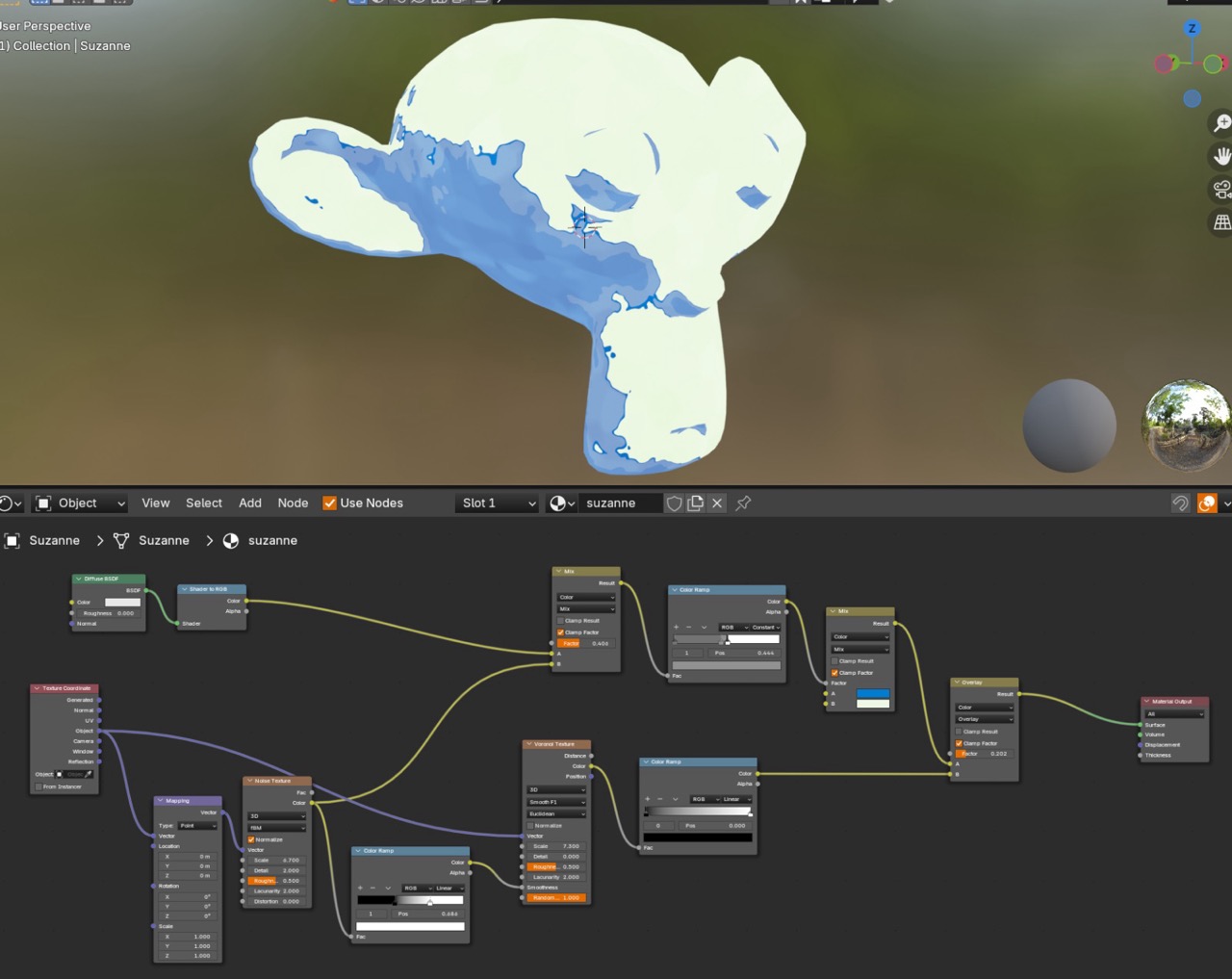
Add the nodes needed to merge the toon base with the watercolor breakup, then route the final result to Material Output.
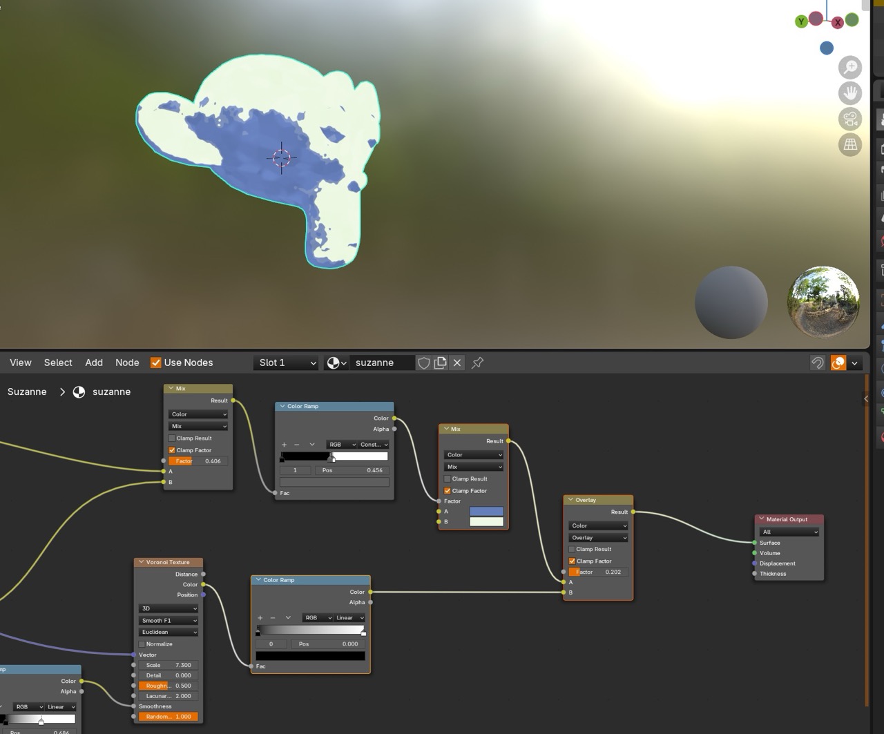
After the first merge, the work is mostly strength balancing and keeping forms readable.
Line art
Line art uses two passes: inverted hull and Grease Pencil.
IV. Inverted hull method
The inverted hull method creates outlines by duplicating a mesh, pushing it outward slightly, and flipping faces so it renders inside-out.
First part: basic outline
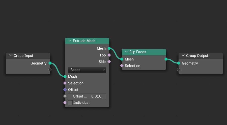
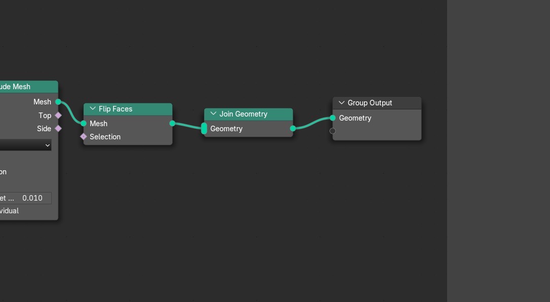
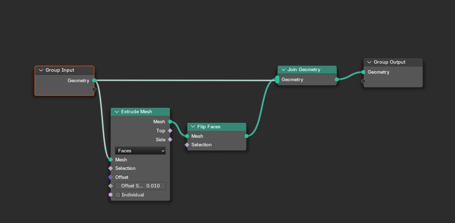
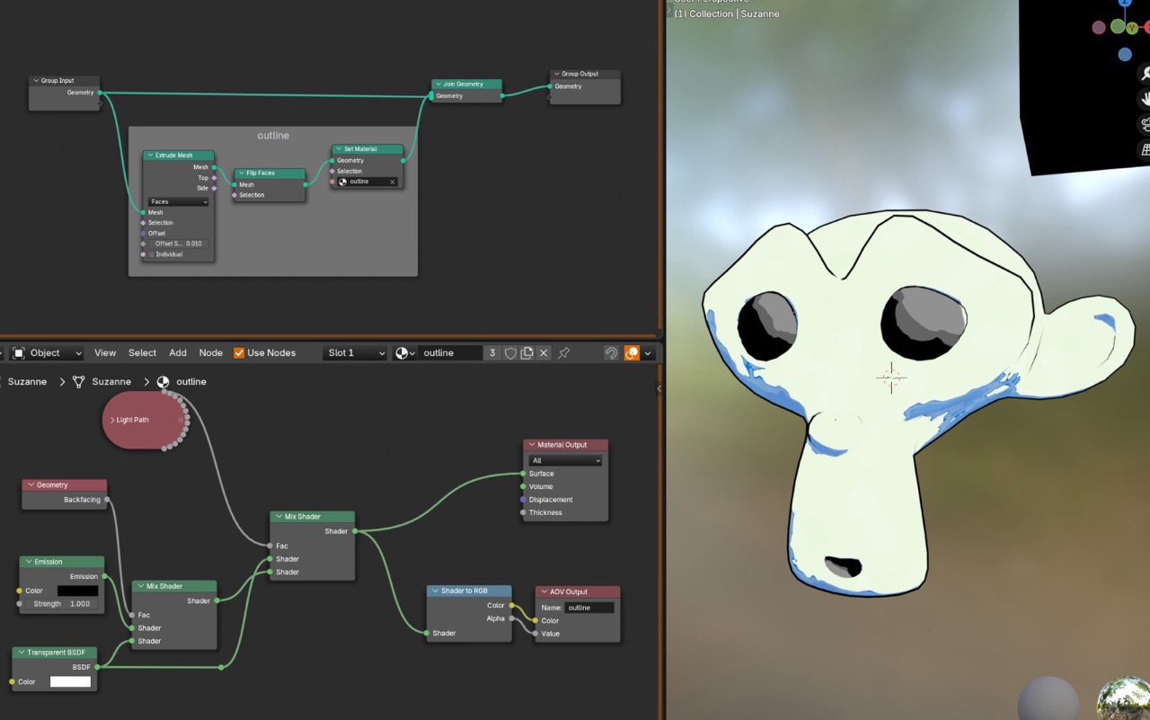
Outline pass 1 uses an inverted hull setup in Geometry Nodes. The core idea is to extrude a shell, flip faces, join it back to the original, and assign an outline material.
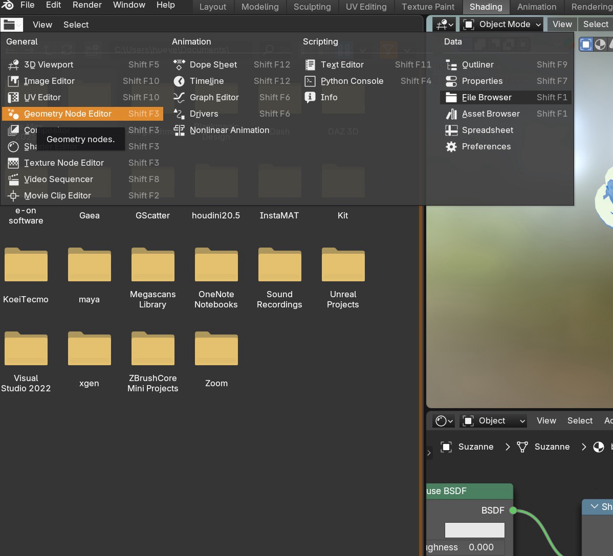
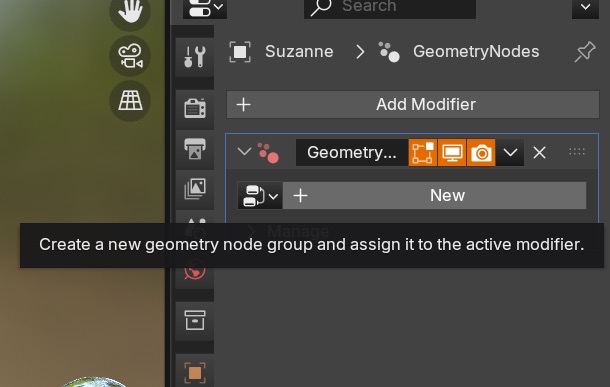
Open Geometry Nodes and add a Geometry Nodes modifier.
Build the base node chain.
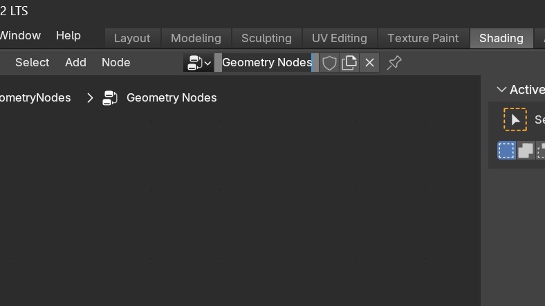
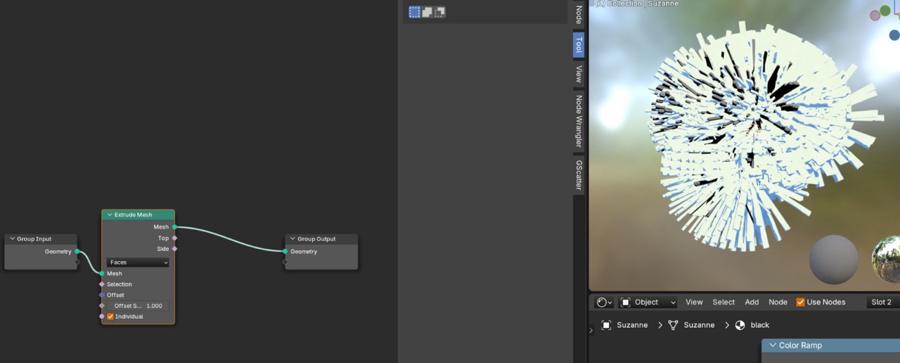
Add Extrude Mesh. Disable Individual. Keep the offset small.
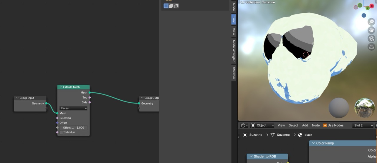
Set Offset to a small value (example shown: 0.01).
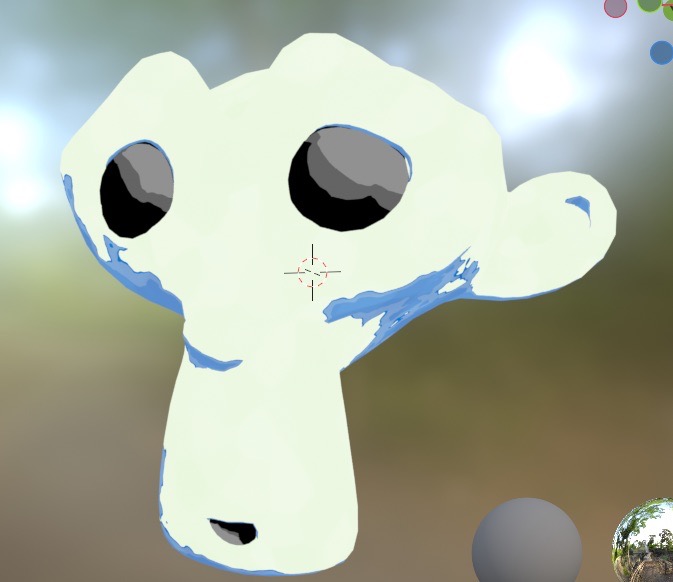
Add Flip Faces, then Join Geometry. Join the outline shell with the original geometry.
Add Set Material for the outline.
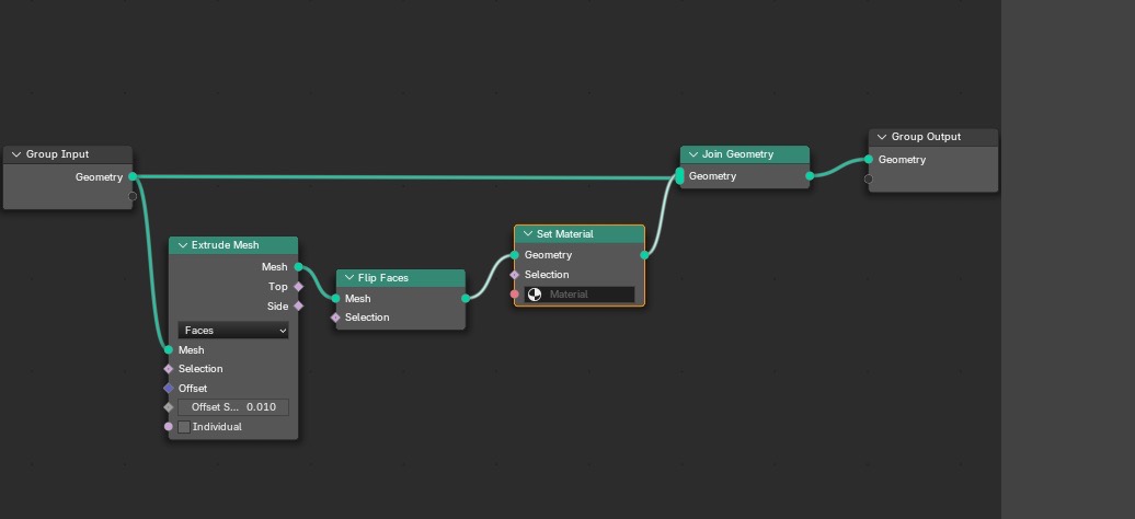
Create the outline material and test it on a simple object.
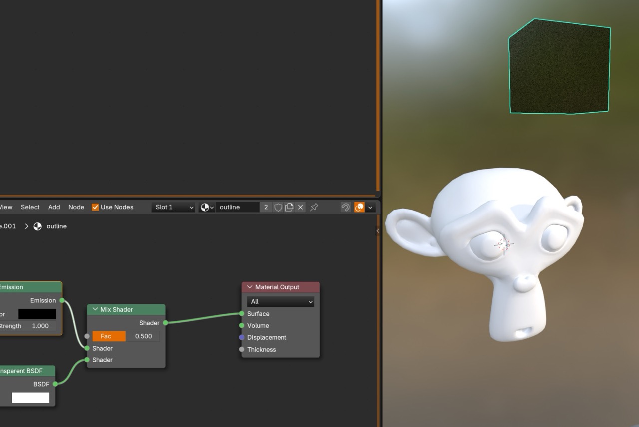
Add the Geometry Backfacing node needed for the outline behavior.
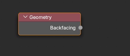
This setup is used to keep the outline behaving correctly in the intended renders.
Add the additional nodes shown, then set up a View Layer AOV with a matching name.
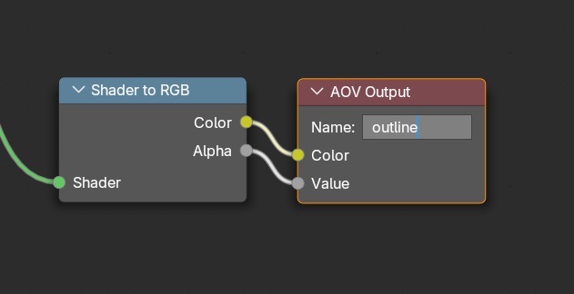
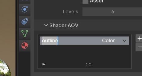
Basic outline setup result.
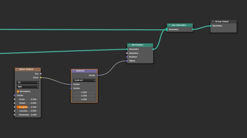
Second part: outline enhancement
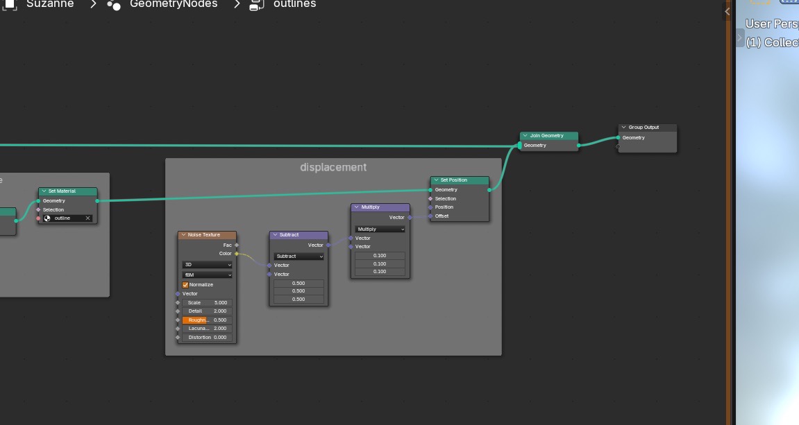
Add the enhancement node group shown. Vector Math is set to Subtract with values at 0.5 to recenter the effect.
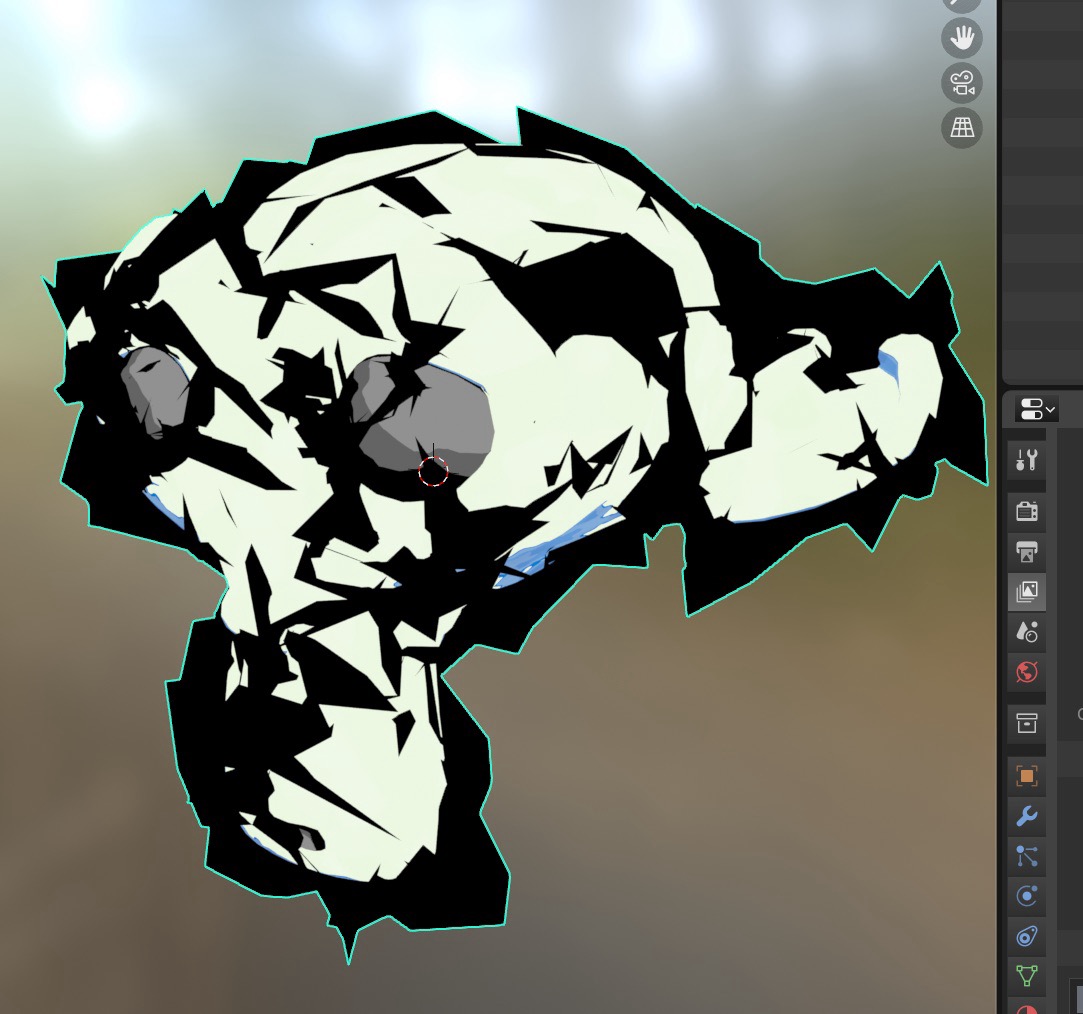
At first the displacement is too strong. This is expected before scaling it down.
Add a Vector Math node set to Multiply and reduce values (example shown: 0.1).
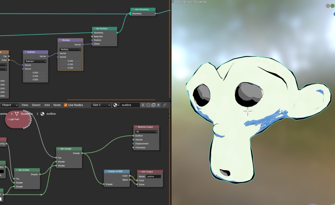
This becomes the displacement group.
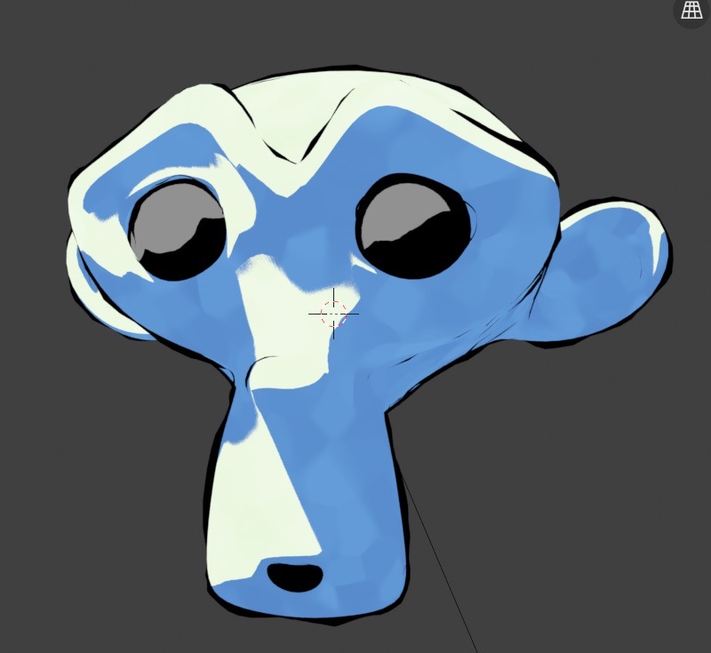
Result check after tuning.
Make the node group more user-friendly
Expose key controls so the Geometry Nodes editor is not required for routine tweaks. The goal is quick adjustment from the modifier UI.

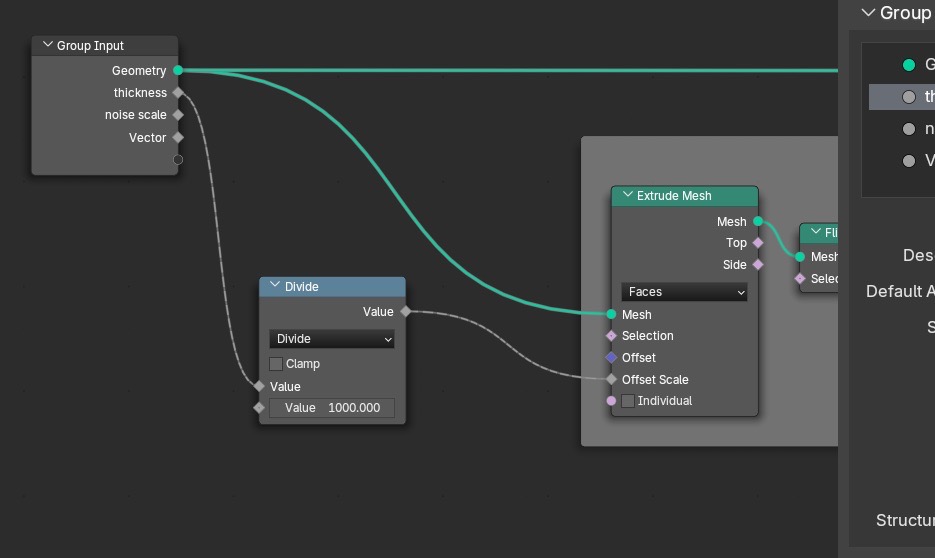
Add a Math node set to Divide and use it to drive offset scale.
Set input defaults in the N-panel (example shown: default 5.5, min 0).
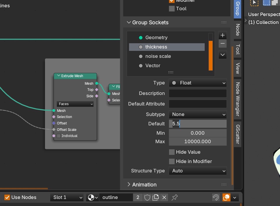
Repeat for the other values.
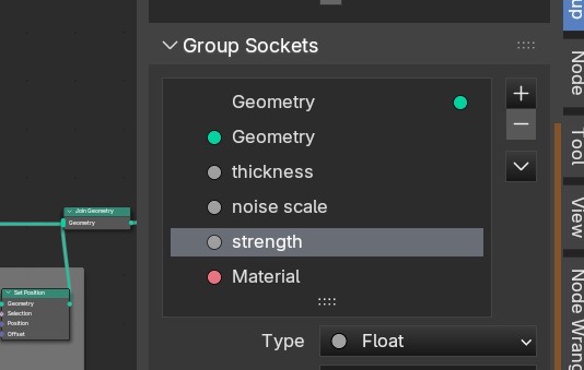
Full setup check.
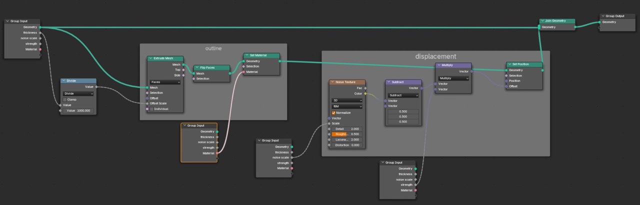
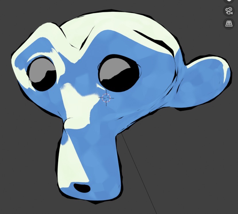
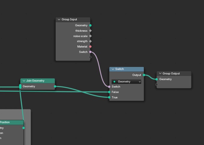
Add a Switch so the outline can be toggled on and off.
V. Grease Pencil
Outline pass 2 uses Grease Pencil for drawn lines, then converts through Geometry Nodes so it fits the same outline and AOV pipeline.
Add a Grease Pencil object. In Edit Mode, clear it. Switch to Draw Mode and draw strokes on the surface.
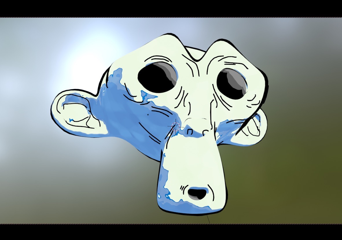
Converting Grease Pencil to mesh (Geometry Nodes)
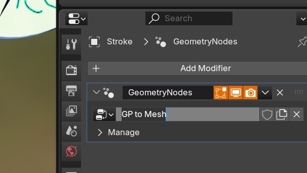
Select the Grease Pencil object and add a Geometry Nodes modifier.
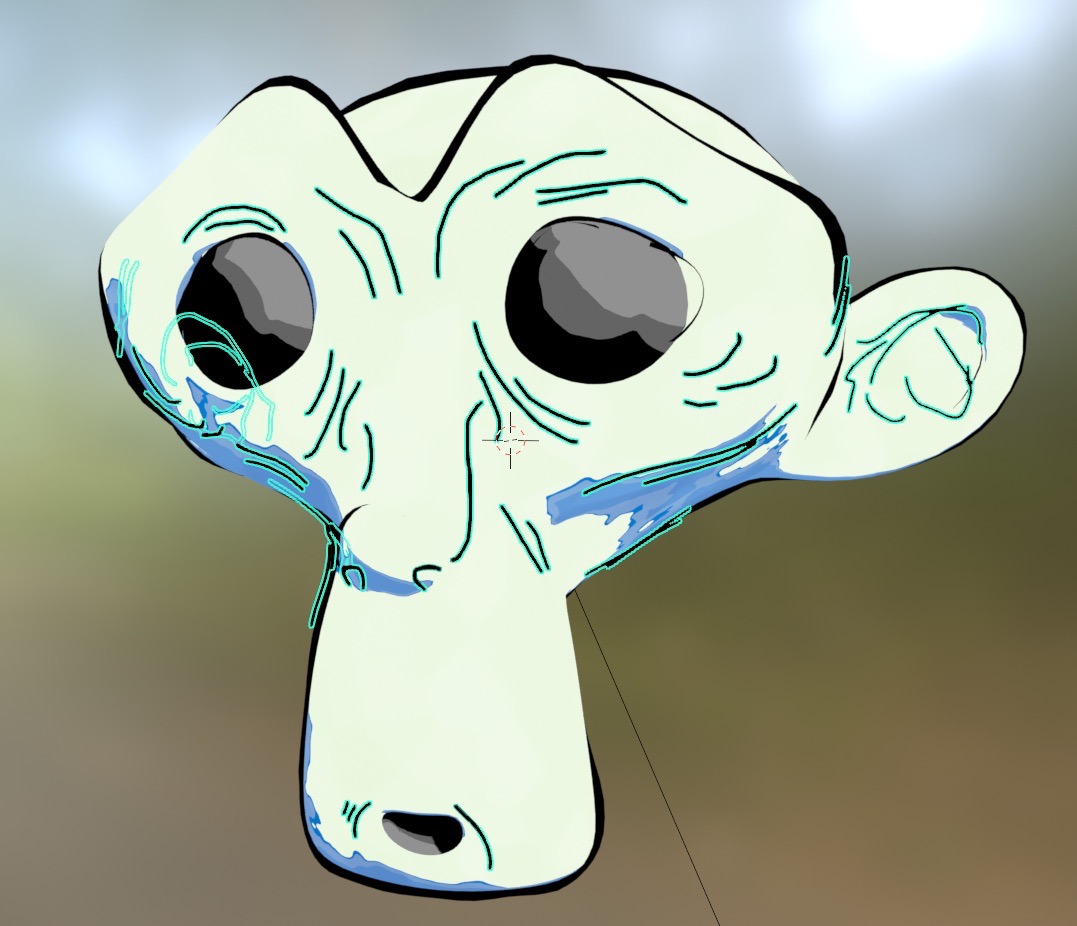
Name the group (example shown: gp to mesh).
Add Grease Pencil to Curves. Disable Layers as Instances.
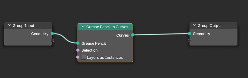
Add the remaining nodes shown until the group matches the reference.
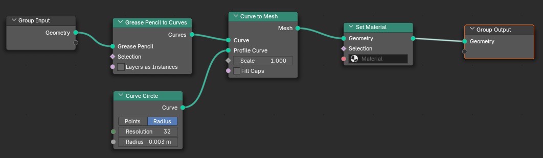
Create a dummy cube and set up the AOV output again. Name the AOV exactly: outline.
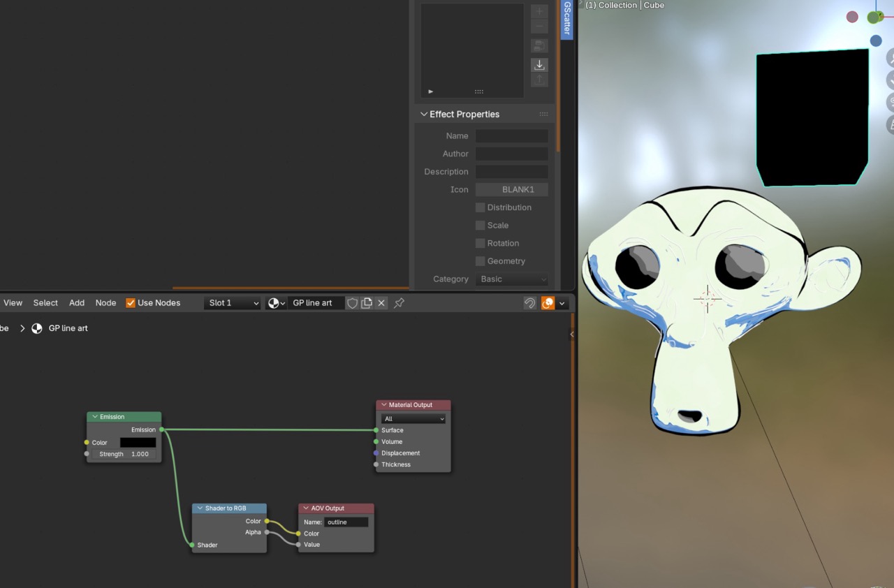
Do the same setup on the Grease Pencil side.
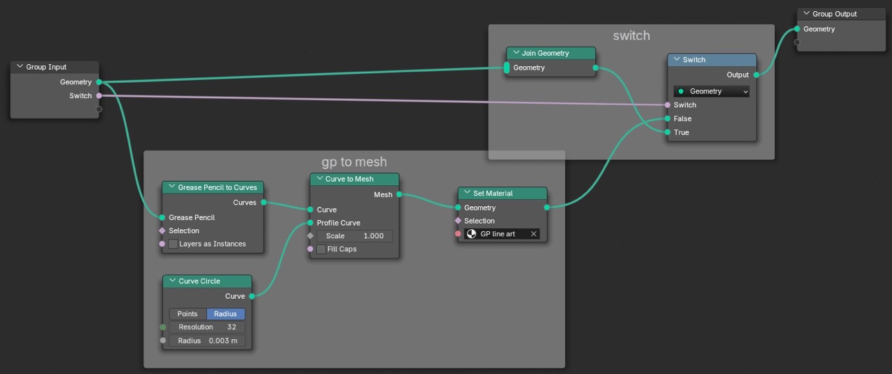
Result check.
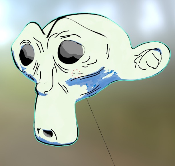
Final check on the combined look at this stage.
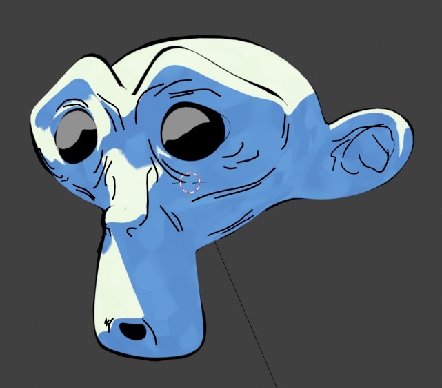
VI. Compositing: tying everything together
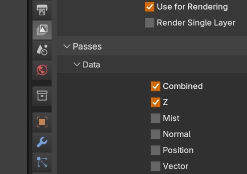
Enable the required passes first, then build the compositor stack.
In View Layer properties, enable Combined and Z.
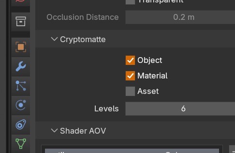
Enable Cryptomatte (Object and Material).
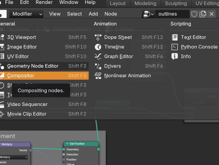
Open the compositor and enable Use Nodes.
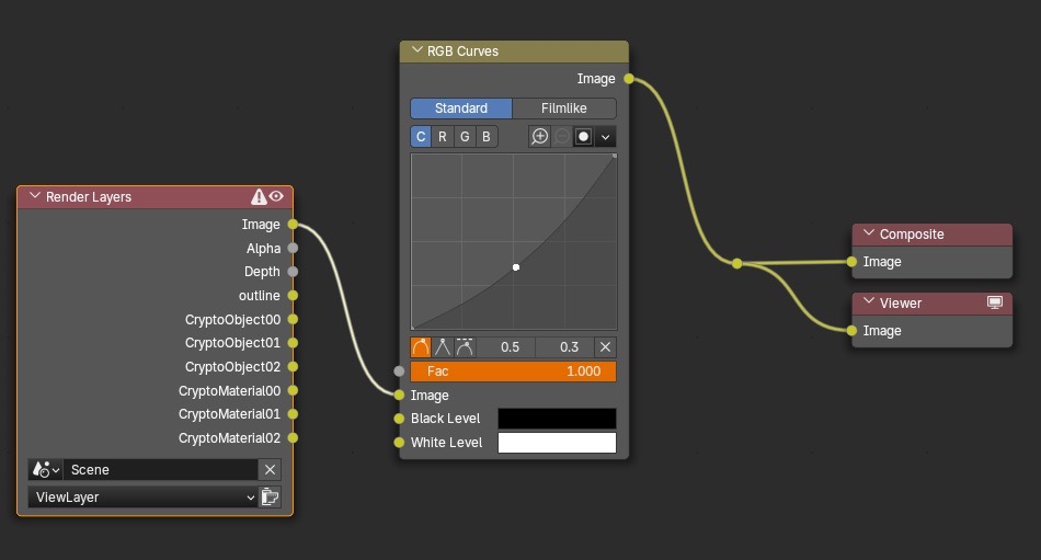
Add an RGB Curves node as a quick sanity check for live viewport updates.
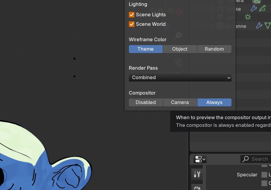
Enable viewport compositing (Always) for real-time tuning.
Live compositor check.
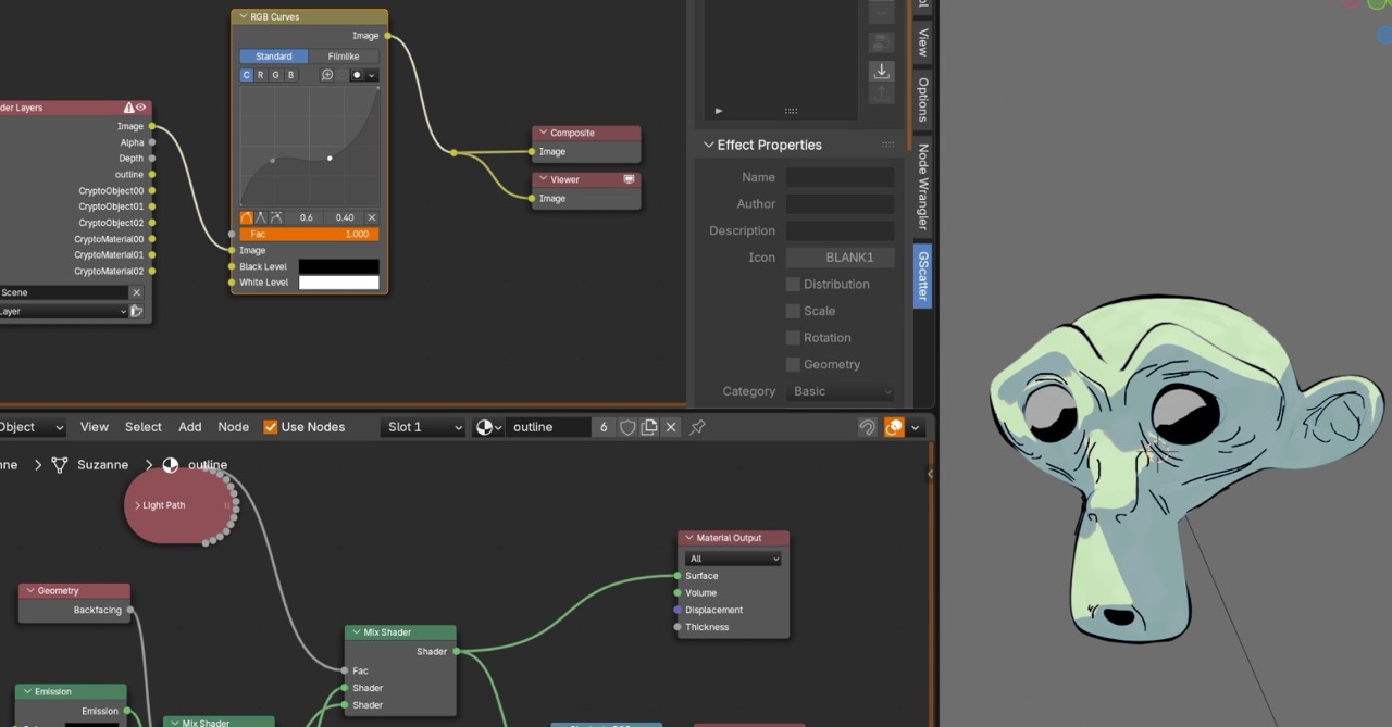
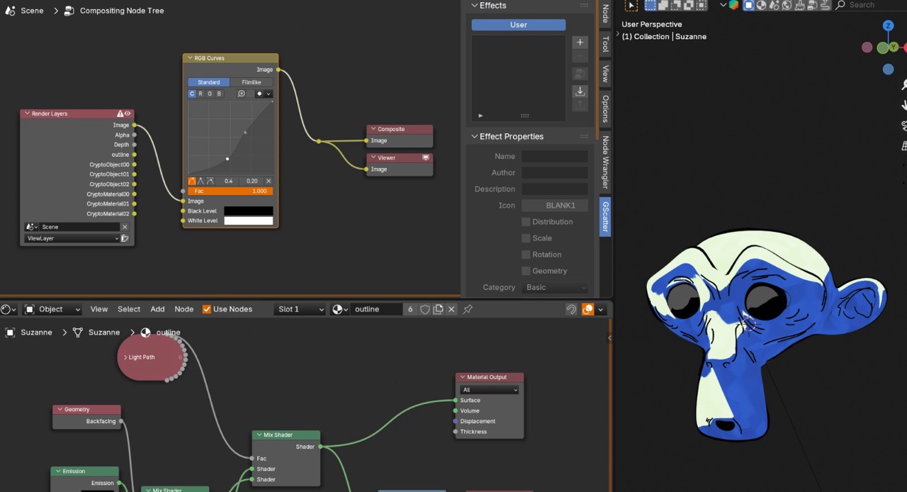
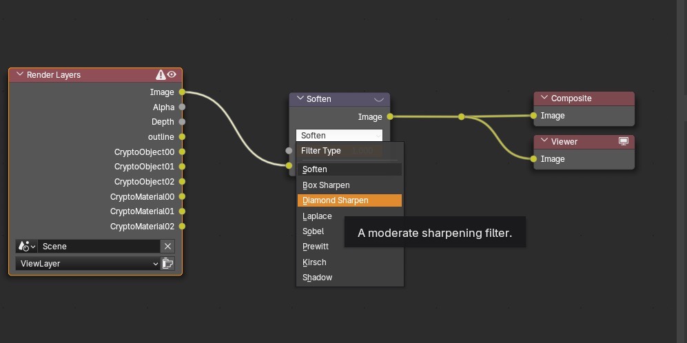
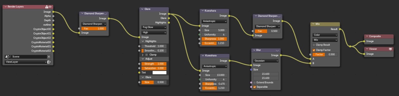
Replace RGB Curves with a Soften node. Set type to Diamond Sharpen.
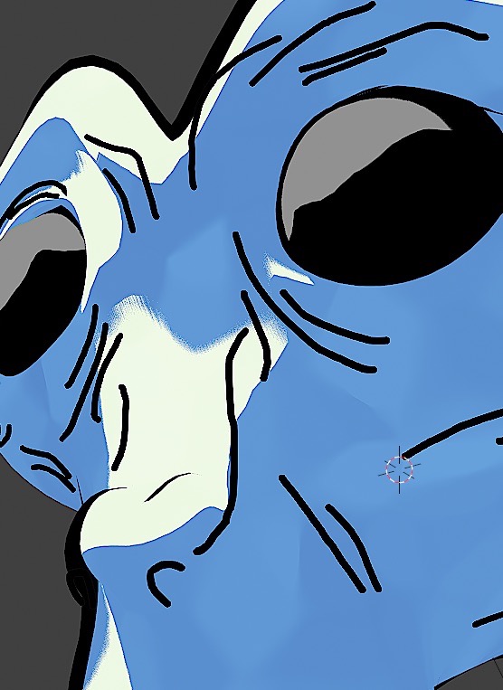
Result check after sharpening.
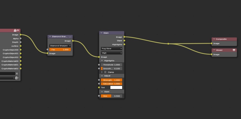
Add a Glare node between them.
Add two Kuwahara nodes and a Mix node between them.
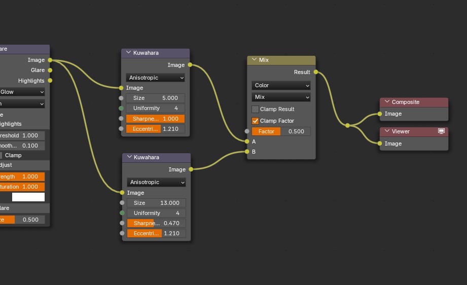
Overview of setup.
Takeaways
- Lock render and color settings first.
- Keep the toon base clean. Control watercolor breakup with a ramp.
- Inverted hull gives stable contours. Grease Pencil adds manual control.
- The compositor is where the look starts to read as paper and paint.